Freedom from nicotine. Built around the ritual.


443H Motor Self-Balancing Differential Protection
Overview
For motors adopting self balancing differential protection motor schemes, medium voltage motor differential protection and the self-balancing differential protection function must be properly configured; this device is applicable to the protection and monitoring of both high‑voltage and low‑voltage asynchronous motors.
Protection Configuration(ANSI)
27/46/48/49/50/51/50N/51N/51LR/59/59N/60/63/81O/81U/87M
Communication Mode
Optional: RS-485, CAN bus, Ethernet, IEC 60870-5-103 (IEC-103), IEC 61850
In-house Factory & Technical Team, OEM ODM Custom Electrical Equipment
Description
Overview
- Self-balancing differential protection for motors is a relatively uncommon type of motor protection implemented by relay for motor protection.
- For motors adopting self balancing differential protection motor schemes, medium voltage motor differential protection and the self-balancing differential protection function must be properly configured; this device is applicable to the protection and monitoring of both high‑voltage and low‑voltage asynchronous motors.
Protection Configuration(ANSI)
- Magnetic Balanced Differential Protection 87M
- Overcurrent Stage I 50/51
- Overcurrent Stage II 50/51
- Overcurrent Stage III 50/51
- Inverse-time Overcurrent 51
- Overload Protection 49
- Stall Protection 51LR
- Negative-sequence Overcurrent Stage I 46
- Negative-sequence Overcurrent Stage II 46
- Negative-sequence Inverse-time Overcurrent 46
- Zero-sequence Overcurrent 50N/51N
- Thermal Overload Protection 49
- Long Start-up Time Protection 48
- Motor Start Blocking
- Overvoltage Protection 59
- Undervoltage Protection 27
- Zero-sequence Overvoltage 59N
- Overfrequency Protection 81O
- Underfrequency Protection 81U
- PT Circuit Break 60
- PT Voltage Loss 60
- Control Circuit Break
- System Power Loss
- Non-electrical Protection 63
Measurement and Control Functions
- Bus voltage: Ua, Ub, Uc, Uab, Ubc, Uca;
- Measured current: Ia, Ic;
- Power: Active power P, Reactive power Q, Power factor COSφ;
- Frequency: f;
- Electric energy: EP+, EP-, EQ+, EQ-;
- Supports 21 channels of active binary input (AC/DC 220V, DC 100V or DC 48V, shall be specified when ordering);
- Equipped with 11 protection output channels, 2 signal output channels, 1 closing position signal output channel, and 1 device power loss output channel.
Communication Functions
Communication Interfaces
- 1 Ethernet port
- 2 RS-485 ports, of which the second RS-485 port is multiplexed with the time synchronization port; communication and time synchronization are selected via configuration.
Communication Protocols
- Internal Ethernet 103 protocol or IEC 61850 protocol, MODBUS RTU protocol.
Time Synchronization
Supports time synchronization via communication messages, SNTP, and IRIG-B.
Setting Table
| No. | Setting Name | Setting Range | Unit | Default Value | Remarks |
|---|---|---|---|---|---|
| 1 | Motor Rated Current | 0.1–100 | A | 5 | |
| 2 | Magnetic Balance Differential Setting | 0.1–100 | A | 5 | |
| 3 | Motor Start-up Time | 0–600 | S | 5 | |
| 4 | Overcurrent Stage I Setting | 0.1–100 | A | 8 | |
| 5 | Overcurrent Stage II Setting | 0.1–100 | A | 7 | |
| 6 | Overcurrent Stage II Time Delay | 0–100 | S | 0.5 | |
| 7 | Overcurrent Stage III Setting | 0.1–100 | A | 5 | |
| 8 | Overcurrent Stage III Time Delay | 0–100 | S | 1 | |
| 9 | Inverse-time Overcurrent Setting | 0.1–100 | A | 5 | |
| 10 | Inverse-time Overcurrent Time Delay | 0–100 | S | 1 | |
| 11 | Inverse-time Overcurrent Type | 0–3 | — | 1 | 1=Normal, 2=Severe, 3=Extreme |
| 12 | Overload Setting | 0.1–100 | A | 5 | |
| 13 | Overload Time Delay | 0–100 | S | 2 | |
| 14 | Overload Type | 0–2 | — | 1 | 0=Disabled, 1=Trip, 2=Alarm |
| 15 | Stall Protection Setting | 0.1–100 | A | 2 | |
| 16 | Stall Protection Time Delay | 0–100 | S | 1 | |
| 17 | Negative-sequence Overcurrent Stage I Setting | 0.1–100 | A | 2 | |
| 18 | Negative-sequence Overcurrent Stage I Time Delay | 0–100 | S | 1 | |
| 19 | Negative-sequence Overcurrent Stage II Setting | 0.1–100 | A | 1 | |
| 20 | Negative-sequence Overcurrent Stage II Time Delay | 0–100 | S | 2 | |
| 21 | Negative-sequence Overcurrent Stage II Type | 0–2 | — | 1 | 0=Disabled, 1=Trip, 2=Alarm |
| 22 | Negative-sequence Overcurrent Stage II Setting | 0.1–100 | A | 1 | |
| 23 | Negative-sequence Overcurrent Stage II Time Delay | 0–100 | S | 2 | |
| 24 | Negative-sequence Overcurrent Stage II Type | 0–2 | — | 1 | 0=Disabled, 1=Trip, 2=Alarm |
| 25 | Zero-sequence Overcurrent Setting | 0.1–100 | A | 2 | |
| 26 | Zero-sequence Overcurrent Time Delay | 0–100 | S | 2 | |
| 27 | Zero-sequence Overcurrent Type | 0–2 | — | 1 | 0=Disabled, 1=Trip, 2=Alarm |
| 28 | Negative-sequence Thermal Coefficient | 2–10 | — | 6 | Default: 6 |
| 29 | Thermal Time Constant | 0.01–100 | min | 5 | |
| 30 | Heat Dissipation Time Constant | 1–5 | Times | 5 | Normally 1~5 times of thermal time constant |
| 31 | Thermal Overload Alarm Level | 10%–100% | % | 80 | |
| 32 | Long Start-up Time Setting | 0.1–100 | A | 5 | |
| 33 | Long Start-up Time Enable Duration | 0–100 | S | 3 | |
| 34 | Start Interval Time Setting | 0–100 | min | 10 | |
| 35 | Low Voltage Block Start Setting | 1–400 | V | 70 | |
| 36 | Overvoltage Setting | 1–600 | V | 120 | |
| 37 | Overvoltage Time Delay | 0–100 | S | 0.5 | |
| 38 | Undervoltage Setting | 1–400 | V | 80 | |
| 39 | Undervoltage Time Delay | 0–100 | S | 1 | |
| 40 | Zero-sequence Overvoltage Setting | 1–400 | V | 30 | |
| 41 | Zero-sequence Overvoltage Time Delay | 0–100 | S | 0.5 | |
| 42 | Zero-sequence Overvoltage Type | 0–2 | — | 1 | 0=Disabled, 1=Trip, 2=Alarm |
| 43 | Underfrequency Protection Setting | 35–60 | Hz | 49 | |
| 44 | Underfrequency Protection Time Delay | 0–100 | S | 0.5 | |
| 45 | Overfrequency Protection Setting | 35.0–65 | Hz | 51 | |
| 46 | Overfrequency Protection Time Delay | 0–100 | S | 0.5 | |
| 47 | Low Voltage Block Frequency Setting | 1–400 | V | 20 | |
| 48 | Slip Block Frequency Setting | 1–30 | Hz/S | 3 | |
| 49 | PT Circuit Break Time Delay | 0–100 | S | 5 | |
| 50 | PT Voltage Loss Time Delay | 0–100 | S | 5 | |
| 51 | Control Circuit Break Time Delay | 0–100 | S | 10 | |
| 52 | System Power Loss Type | 0–2 | — | 1 | 0=Disabled, 1=Trip, 2=Alarm |
| 53 | High Temperature Alarm Time Delay | 0–100 | S | 0.1 | |
| 54 | High Temperature Trip Time Delay | 0–100 | S | 0.1 | |
| 55 | Non-electrical Protection 1 Type | 0–2 | — | 1 | 0=Disabled, 1=Trip, 2=Alarm |
| 56 | Non-electrical Protection 1 Time Delay | 0–100 | S | 0.1 | |
| 57 | Non-electrical Protection 2 Type | 0–2 | — | 1 | 0=Disabled, 1=Trip, 2=Alarm |
| 58 | Non-electrical Protection 2 Time Delay | 0–100 | S | 0.1 |
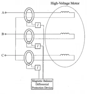
motor differential protection diagram
Outline and Installation Dimensions


FAQ
Q:What tests must be performed on motor differential protection devices before they are officially put into service?
A:Before putting digital motor protection relays into service, multiple tests such as accuracy verification, functional inspection and motor differential protection stability test must be carried out; only after meeting specification requirements can the relay motor protection systems be officially commissioned.
Related products
-

ASD-441H Motor protection relay
The ASD-441H Motor protection relay is primarily designed to protect motors.It is suitable for high-voltage motors in 3 kV to 35 kV systems, and serves as bay-level equipment, performing protection, measurement, control, and communication functions. Product Functions (ANSI) 50/51/46/47/48/49/27/50N/51N/59/66/60/74 Communication…
-

Motor differential protection 87M
Overview The motor differential protection device adopts professional differential motor protection logic. It is an integrated protection and control unit developed for high- and low-voltage asynchronous motors, available for standalone panel installation or built-in mounting in switchgear cabinets. Product Functions…
Reviews
There are no reviews yet.